Saturday, 14 December 2013

RC Car Updates 12/14: Almost there!


Hello everyone!

I have been very busy with finals so I didn’t get the time to share more updates with you. I have been making solid progress in the project. I would say that the car electronics are pretty much completely done. I am thinking I might ditch the proximity sensor even though I own one already. I just can’t think of a good place to place the bulky sensor on the car’s body. Here is what my proximity sensor looks like:


Picture of the Proximity sensor in question.

On the other hand, I have already started designing the remote controller. If you remember, I had purchased an off-brand Xbox controller. I actually changed my mind on that too and decided to base my designs off of the original Microsoft Xbox 360 wireless controller. I was lucky enough to get a controller donated to me from a game store (Huge thanks to Jeff and his buddy!). I also bought a controller shell in which my PCB will go. It is really easy to find design notes and spare parts for Xbox controllers since they are so common. EBay proved to be the perfect place for looking up Xbox controller parts.


Xbox 360 controller shell w/ parts I purchased.

However, the biggest challenge in creating a PCB that is compatible with an Xbox controller shell is that the board needs to have perfect dimensions and perfect hole/part placement. Also, the board has a non-rectangular shape, so it is very tricky to get it right. There are many obstacles on the shell so there are many keep-out zones I need to watch out for on the board. Each fab run of this board at this size will cost me about $45-50 so I need to get it right on my first try. I cannot mess up the design, or there will be very expensive consequences.


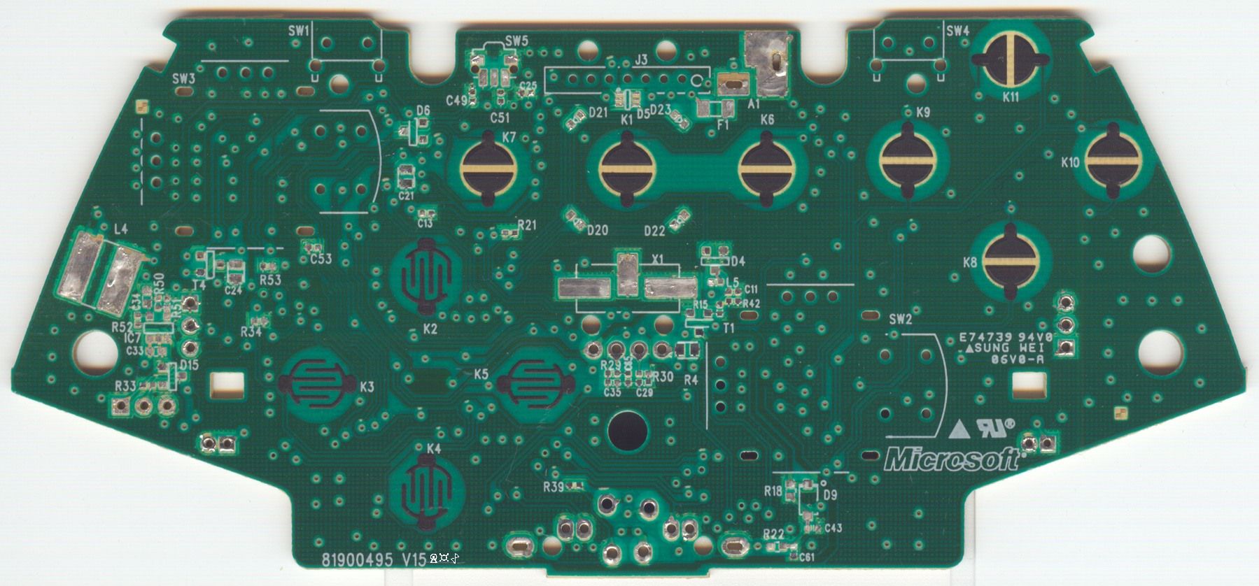
A scan of the Microsoft Xbox 360 controller PCB. (Source: RDC from Acidmods)

RDC on Acidmods.com has been very kind and has been helping me with the design of the controller PCB. He has created an Xbox controller-compatible PCB before so his knowledge is very insightful. I have also purchased one of his boards called “36X controller” and have been referencing that when designing mine. Because the dimensions are very tricky, I have been using MATLAB to accurately retrieve measurements. It would be pretty much impossible to retrieve accurate dimension measurements using a caliper from the actual board with all the parts on it. RDC actually sent me a screenshot of his own design, and using MATLAB, I am measuring the distance between 2 points at a time in pixels. With a calibration measurement, MATLAB converts pixels into millimeters which then I use in Eagle to place my components. As an experiment, I printed out a 100% scale copy of my PCB from Eagle and laid it over RDC’s 36X PCB and got a perfect match! All holes, critical components are exactly where they need to be. So the MATLAB technique seems to be working great.

3-D Rendering of RDC's X36 PCB. (Source: RDC on Acidmods)

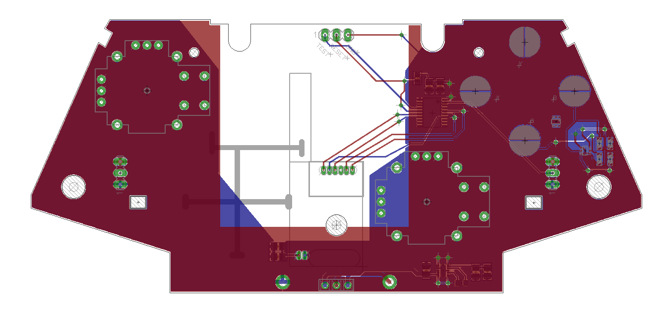
Screenshot of the current state of my remote controller PCB. 

As for the car itself, everything is installed. There are now 2 stand offs that hold the main PCB in place. Also, my super glue solution for keeping the servo in place has failed. So my friend Jeff was nice enough to drill some holes on the car frame so that we could screw down the servo in place rather than depending on glue to hold screws down. You can never go wrong with the old washer/screw/nut combination. Finally, all the LEDs are installed and they work perfectly. They are very bright, and brake lights operate just like they do in a real car. Jeff and I are currently considering installing some police lights on the roof of the car just to make it more bad-ass. Lastly, I will be sanding down the paint on the body of the car and repainting it. I am thinking of painting it matte black, I think it would look very cool. And I want to leave you with these 2 pictures of the car, notice the lights!


Thursday, 14 November 2013

RC Car circuit is now on wheels!!! RC Car Updates 11/14

Hey everyone!

Awesome awesome news! But before that, quick apology for not posting in over a month! The project is still a go at full speed and I have been making huuuuggeee progress.

The circuit board is NOW ON THE CAR! I have made the necessary modifications required to integrate the circuitry to the car chassis. The first mod required was the servo swap. The RC car originally came with a DC motor to steer the front wheels. This is a very inefficient way of achieving steering since it counts on the motor stalling and keeping the wheels fully locked to the either side. This means you get no control over where exactly your wheels are pointing and the stalled motor pulls billions of amps!

The servo swap required me to use some machinery to get rid of the old fasteners that held the DC motor in place. After I got rid of that, I had to drill a new hole through which the servo went through. Finally, I did have to extend the gear piece that came with the servo, by super-gluing another piece of plastic which finally connects to the steering column.

Here is a close up of what it looked like right after I did the servo swap. I did unfortunately use super glue to glue down a couple of nuts to the body on which I screwed the servo in place.

Right after I finished the servo swap.

Before the standoffs and the battery holder were installed.

After the servo swap, the next modification needed was to mount stand-off's on which the circuit board could sit on. For this, I needed the help of my buddy Jeff who has a friggin' wood-working/machine shop in his basement! We got a pair of standoffs that was quite what I needed to we used his tools to modify the standoffs until they became what I wanted :) The standoffs are screwed into the chassis of the car and the circuit board screw into the standoffs. Here is a picture of the car when we were drilling holes into it.

Picture of the car in Jeff's shop.

There are only 2 standoffs and they are both on the same side, however the battery holder also supports the circuit so it should be fine. Speaking of the batteries, I have purchased 8 2300 mAh Energizer AA batteries from Amazon. These are the batteries that powering this bad boy, and I also got a very nice battery holder for them. The battery holder unfortunately does not fit in the original compartment where the old battery used to go, so it sits on top of the old battery compartment. The holder is Velcro'ed on top of the old one and without too much hassle, it is possible to reach the batteries inside without having to deconstruct the whole car. It is still somewhat of a pain in the ass though!

Finally, I do have a demo video for you. Enjoy:


Thanks!

Sunday, 6 October 2013

Great Milestone: RC Car Updates 10/6

Hey everyone,

This is a big milestone in the Crazy Fast RC Car project. The PCB actually works!! There is not a single thing that I messed up on it! I am baffled by the fact that this board works the way it does considering it is only the first revision. We can count this on the numerous times I checked the wires and the connections on the board in Eagle before I got it fabbed, it all paid off.

I must say that I got very close to making a colossal mistake on this board when I was designing it. As you know, there are two LDO regulators on the board, one for the 5V bus, and the other for the 3V3 bus. For the 5V bus, I am using a beefier version of a LS7805 with the same pinout. For the 3V3 regulator, I had originally purchased an LM1117. However, I thought that LM1117 had the same pinout as the LS7805 regulator. It turns out that GND and VOUT are swapped, so this gave me a momentary heart attack when I found out. I thought I would have to fix this and have to get a new revision of the board fabbed, but I was very lucky to find that NTE1904 (which is a 3.3V regulator) has the same pinout as a LS7805. So I ordered one and soldered it on the board and it worked.

I am still waiting on the dual row female headers I purchased 3 weeks ago. I was being cheap and decided to order from China, not knowing it would take this long. I am getting pretty impatient, but once it arrives, I will solder that on the board and have a chance to test all of the functionality of the board. Namely, I still need to make sure my wiring and the voltage divider I made is working as I planned for the optical sensor. You will see in the video that the remote controller device is still on a breadboard. Once I finish up the Main RC Car board, I will start working on a PCB design for the remote controller also.

Go ahead and watch the video below:


Sunday, 22 September 2013

RC Car Updates 9/22: Soldering components on a PCB

Hey all,

I have been soldering the components on the board this past weekend. Soldering can easily become a nightmare when you have a lot of components, especially if they are surface mount parts.

Surface mount parts are much smaller than through-hole components and their footprints are usually much smaller. This makes it very hard to solder surface mount components when compared to their through-hole counterparts. One might choose to use surface-mount (SMD) components over through hole components when space is a limitation on the board. Also, because SMD components are on the "surface", they take up space on only the layer that they are on. Through hole components require "through holes" to be mounted so the hole goes through all of the layers. This means that you can't use the space underneath the component to route wires.

Space became an issue in some areas of my PCB therefore I had to choose SMD parts. However, I tried to use as much through hole components as possible to make soldering easier. There are some simple rules that I follow when I solder up a board. First, I solder the SMD components before I solder the through hole components. The reason is that I use a technique called "reflowing" to solder the SMD parts. This technique requires solder paste, which kind of speaks for itself. It is like solder but comes in a paste form. You apply the solder paste on all of the SMD component footprints first. Usually, you would use what is called a stencil to make this process easier. Stencil is basically a mask for your PCB with only the footprint areas exposed. Then you would use a spatula to apply the soldering paste which would automatically find its way to the footprints. However, stenciling is quite expensive so I did it the manual way. I applied the solder paste on the footprints using a toothpick being very careful and slow. You want to make sure you don't short footprints together by applying too much solder paste. Once this is done, you carefully place the SMD components on the solder paste-applied footprints. Using tweezers are highly recommended for this step.

Once all of the SMD parts are placed, next step is quite unusual: heat up the board. I know some people use heat guns, frying pans etc. I use frying pans. Turn on your stove and let it heat up the frying pan. Then add the main ingredient: the PCB. I really cannot tell you how long to keep the board on the PCB, but how I know is I watch the solder paste. The solder paste is usually gray colored, and when it is "done" it turns into a silver color just like regular solder. This is when I know my PCB is done cooking!! Check out the picture below:

When the soldering paste turns silver, remove the board and let it cool down. Once it is cool to touch, you can start soldering the regular through hole components. I am not going to talk about how to solder, that is very trivial. But I want to share the current status of the board with most of the components soldered.


You will notice that the 3.3V regulator is not populated on the board.... Unfortunately I messed up a little there. I now understand why people say "the first revision of a PCB never works". But mine will!!! It is a recoverable error. I miscalculated the pinouts of the 3.3 V regulators I ordered but I did find that RadioShack sells 3.3V regulators that will work with my board! So I ordered a new regulator right away and I will solder it when I get it. 

Other than that, the only parts I am waiting for are the dual row female headers for the C2000 LP to sit on and SMD LEDs. I have obviously soldered many through hole components already, so I will not be reflowing the LEDs. It also turns out I am very short of through hole ceramic capacitors so I need to order a bunch of those. Overall, project is going really well so check back for more updates! I should be able to test the board in a couple of weeks!

Anil

Thursday, 19 September 2013

Crazy-Ass Fast RC Car Updates 9/19

Hey everyone,

Quick heads-up: The name of the RC car project has officially changed to Crazy-Ass Fast RC Car.

I am happy to report that my boards are finally in! The PCBs were fabbed in China through SeeedStudio. I highly recommend their service to everyone. The boards seem to be really high quality and well built. Despite the really low price, they are looking really sharp. Also as a plus, I received 9 copies of the board even though I ordered 5 boards. So they are also quite generous.

I haven't had a chance to populate the boards yet. There are going to be a lot of components on the board, so it is taking a long while to gather everything needed. I am on a tight budget so I am buying most of the components on eBay shipped from China. The footprints are spaced out perfectly for the C2000 LP! Boards are looking very promising.

Here are some pictures:

Fresh out of the oven.

C2000 Launchpad Sitting on the footprints


Wednesday, 28 August 2013

RC Car Update 8/28

Hell Everyone!

It has been almost 1.5 months since the last time I posted an update! There is finally an update now, and here I am sharing it. The main PCB that will go into the RC Car is ordered! I am using Seeed Studio PCB services to get my board fabricated. The board is about 8cm-10cm, and I am paying $30 in total for 5 copies of the board.

I have finally added the features I have been meaning to add onto the board and created the Gerber files. After carefully reviewing them, I decided it was good to go! I placed the order and paid for it about a couple of hours ago. Bad news is that the boards are being fabbed in China so it could take up to a month until they actually reach me. This my first time working with Seeed Studio's PCB service so I will make sure to let you know how it goes.

On top of that, I have also ordered the transistor that will be used to switch the headlights on the car, the 5V and 3.3V LDOs that will supply power to the components on the board. I am really excited to see that this board is finally getting fabricated after working on it for 4-5 months! I am planning on posting another update when I get the boards from Seeed.
3-D rendering of the main RC car PCB.

Tuesday, 9 July 2013

RC Car Updates 7/9!!

I have another demo today. I have been making solid progress in this project. I am going to keep this one short, so let's get to it.

What's new:

  • The motor controller prototype that I finished building last month is finally being utilized. It is now doing what it is meant to do. The C2000 is fully interfaced with it over MotorA, MotorB and GND lines. I am now utilizing the vertical axis of the joystick to control the DC Motor. Click-in of the joystick does motor braking (very cool).
  • I purchased a DC motor. I bought it just so I could try out the system. It is very big, but not probably not the most efficient or the fastest motor. So it will do for now, but for the real deal, I am going to invest around 20-30 dollars for a very high speed DC motor. I will throw heat sinks on all transistors, so I should be able to pull 5 Amps continuously. (The only limitation is cooling...)
  • I purchased a new servo motor. This servo pulls 1.4 Amps when the rotor is moving so I had a hard time finding a power supply beefy enough to power the servo. When I try to power it from my PC or my 1-Amp phone charger, when the servo pulls current, voltage drops and the C2000 does a brownout reset, kind of funny :)
Aaaaannd here is the demo. Enjoy ;)


Friday, 28 June 2013

RC Updates 6/28 - Awesome Demo!

Hello Everyone!

I have an awesome demo for you all today. I have been busy with other things lately, so haven't had time to post on the blog. However, Christmas came early and I got a highly-anticipated package in the mail today. I dropped $40 on Sparkfun 3 days ago and bought the IR Proximity Sensor I talked about in one of my earlier posts, 2 thumb joystick breakout boards, Lead-free solder paste for reflowing, and SOT-23 breakout boards.

If you remember, I bought a PS3 controller about a month ago. I disassembled it and desoldered one of the thumb joysticks on the controller (desoldering was such a pain, can't even describe it...). So I grabbed a couple of joystick breakout boards from Sparkfun which I received today.

In addition, while I was away from the blog, I did crack the RF modules! I don't remember if I mentioned this in a previous post or not, but RF modules are up and running, so the firmware is really taking shape. The remote unit firmware for the C2000 LP is running SYS/BIOS and is PWMing three seperate pins. One of the pins is the servo control pin, and the other two PWM pins are going to the motor controller (the thing on the breadboard I demoed with an LED a month ago). I don't have a motor here with me, but with these 2 PWM pins, I should have decent speed control of the car.

Time for the demo!! I am not going to say anything, just watch it. It is pretty awesome.


The dead-zone issue is now fixed so the servo doesn't spaz out while it's idling anymore like it was in the video. Let me know what you think, I am pretty excited to see the project taking shape.

Thanks!

Wednesday, 5 June 2013

RC Car Update 6/4

Hey everyone!

I haven't posted in a week but I have made some major progress in the meantime. Let's get right to it!

I received my first set of PCBs from OSHPark last friday! They look amazing and the dimensions seems to be perfect. I had to measure the distance between the two sets of pins on the RF module so I was worried that the pins on the module wouldn't match the holes on the board, but it was a perfect match! I did screw up one thing though, the silk screen with names of the pins were wrong. Because the pins were mislabeled on my board, my MCU couldn't talk to the RF Modules and it took me too long to find out that it was a simple labeling mistake... If I ever make rev 2 boards, I will be sure to fix that. And I am thinking about reducing the ground plane dimensions so it doesn't span the area near the RF antenna as that causes a  decrease in the wireless performance. But here are a few pictures of the board!


I am able to talk to the RF Modules using SPI, and it turns out SPI is a very easy and fast interface, so it is recommended to everyone! The only problem right now is that it turns out I don't have enough female-female jumper cables so I can't connect up the both modules at the same time. So I haven't yet tried to actually get the RF modules talking to each other. No worries, the jumpers are already in the mail.

The firmware is also coming along nicely. I am building a library of drivers for the CC1101 RF Modules for both of the launchpads, the C2K and the MSP430. The C2K library is compatible with SYS/BIOS which is running on my C2000 firmware, and with small modifications it works on the MSP430 LP. I am done with the core functionality required for basic communication, so I will make the MSP430 LP talk to the C2K LP over RF once I get my jumper cables.


Also, I purchased a PlayStation 3 controller which I will modify and make it into the controller of the RC Car! The controller is not a Sony brand controller, but an off-brand one. However, the cheaper the controller is, the easier it is for me to work with it. I already tore apart the controller to see what's inside and how much room there is inside. I suspect the spiral antenna of the RF Module will have to stick out of the controller since there is not enough room to fit it all in there. The controller has a slot for 3 AAA batteries, and I will use a TI Buck-Boost converter TPS63031 which is able to up/down convert to provide a stable 3.3 V power source. And as I mentioned before, an MSP430G2553 will be in the controller. I might go for a surface-mount package rather than DIP, but I don't trust my soldering skills, so we will see depending on the space limitations inside the controller. Here is a picture of the controller, assembled and disassembled:


Power A Pro PlayStation 3 Controller


Controller Assembled

Space in the controller is limited unfortunately. I will design a PCB with the same dimensions and shape as the board seen above, but with my own circuitry. One down-side with this controller is that the triggers aren't connected to potentiometers, they are basically tactile switches, so it is either pressed in or released, and nothing in between. I was hoping to make one of the triggers the throttle for the car, but I can't do it with this one. So I will make the left joystick throttle control and the left joystick will control the steering. One of the push buttons will become motor brake and another will be used to toggle the LEDs on the car. Thanks for reading and do comment below!

-Anil

Monday, 27 May 2013

Building an RC Car Update 5/27

Hey all,

There are many updates! I have been working on the revised motor controller circuit board for weeks now. If you remember, I shared the screenshots and rendering of the original motor controller PCB a few weeks back. However later on, I decided to integrate the C2000 Launchpad, all the pin outs for external components and the motor controller on the same circuit board. So I have been working on this revision and here it is! The following pictures are OSHPark renderings along with 3-D image renderings. Let me know what you think! OSHPark quotes me $60 for 3 of these boards but it looks like I can get 5 of these boards for about $20 from Seeed Studio.


3-D Renderings of the Board. Notice the two sets of double headers where the Launchpad will sit on. 


OSHPark Renderings of the board.

Before I send it out to the fab, I still need to do a few more proof of concepts. First of all, I am still waiting on the breakout boards I made and ordered for the CC1101 Wireless modules. I figured out how SPI works on the C2000 and got it running on SYS/BIOS talking with my Aardvark SPI/I2C Monitor. Now all I need to do (once I receive my breakout boards) is get those wireless modules working! I have been reading the datasheet and I have a rough idea of what I need to do so we will see how it goes.

Major Addition:
I was talking to my dad about this project and he came up with a great idea! He suggested that I add a proximity sensor on the car to avoid collisions. I thought that was a great idea and found this SHARP IR Proximity Sensor. Basically it is an IR emitter and detector coupled in one package that spits out analog voltage between 0-5 V. I will pass that analog output through a voltage divider network to make sure it doesn't exceed 3.3 V going into the ADC of the C2000 Launchpad. So I will place this sensor on the nose of the car where the front bumper is and it will automatically brake the rear wheels if it senses an obstacle that is less than 5~7 inches away. Here is a picture of the sensor:
Sharp IR Sensor capable of sensing obstacles up to 80 cm away.

With the fast motor I am eventually planning on putting on the car, it is a good idea to have this sensor to "preserve" the car. I am really excited about this and I have already compensated for the sensor connections on the main circuit board that I shared above. Thanks for reading and please let me know what you think!

Edit: I just noticed the 3-D renderings differ slightly from the OSHPark renderings. The OSHPark renderings depict the most recent state of the circuit.

Saturday, 18 May 2013

RC Car Updates 5/17

Hello!

I have a video for you guys today. In the video below, I demo the motor controller prototype for you guys. I have temporarily relocated to California and I couldn't bring the RC Car frame with me here. The frame has the main DC motor on it, and I haven't been able to take it off, so to bring the motor, I would have to bring the whole frame which is way too big. As a result, you will see in the video that I don't have a motor to connect to the motor controller. I did manage to PWM the motor using the C2000 LP before I left for California, so that does work. I am using a pair of LEDs connected in parallel with opposite polarity to prove that current does run in both directions. Sorry for the lame demo, motor spinning would definitely be cooler than a pair of LEDs blinking.


On the other hand, I am going to start working on cracking the RF transcievers I have. As I mentioned earlier, the RF modules came with 0.05" pitch header connectors which are useless, so I had to build a PCB using Eagle to make a simple RF Module Breakout board. Renderings shown below. I actually just ordered these boards from OshPark an hour ago. I am very excited since these are the first ever boards I have ordered! For three of these boards, I paid only $5, so that is a good deal. For my next PCB, I want to try out Seeed Studio. The next board I will build will be quite large since it will incorporate the motor controller, headers for the C2000 Launchpad to sit on, and other pins to connect the external peripherals (Servo, LEDs...). I reckon if I use OSHPark to get that PCB done, it would cost about $40-$50 which is a lot. Seeed studio is much much more reasonable and I got this tip from a colleague at work (shout out to Stephen!)

 OshPark PCB Top rendering.

 OshPark PCB Bottom rendering.

I have an Aardvark SPI/I2C Bus monitor with me here, and for initial protocol testing I will be using it. Later after I figure out how the communication carries out, I will start working on the drivers for the C2000 LP. The protocol is SPI and I am not worried much about that, what worries me is the abundance of registers in the RF Modules and the 100-page datasheet. So I will need to figure out how I need to set up the internal registers in the RF modules (set one as a receiver and the other as a transmitter and tune them to correct channels, set up error connection, etc.....) The advantage of Aardvark is that I will be able to send commands to the RF Module over SPI from my computer. Therefore, I will be able to see all the communication taking place on my computer in a terminal which makes debugging much easier. I will keep you updated.

-Anil

Tuesday, 14 May 2013

RC Car Updates 5/14

Here are some more updates on the project. In my last update post, I pointed out that I was waiting on one last part to complete the prototype. I was actually waiting on some 2-to-4 decoders and I received them almost 2 weeks ago. As soon as they arrived, I popped one on the breadboard and constructed the circuit that I shared as a design drawing 2 posts ago. I was so surprised but it "just" worked!! I didn't have to tinker with it or anything, I just went by the design and it worked. I actually started on the software also, I will talk more about that later on. But I connected up the motor to it, and connected the two motor controller input pins to my microcontroller and applied a PWM signal, and it worked!!

More about the microcontroller side of the project: This is the first project that I am building that is using TI's C2000 Launchpad Microcontroller. This launchpad, which I believe is the second Launchpad that TI released, uses the C2000-F28027 Piccolo Microcontroller. It runs at 60 MHz, and it is capable of UART, I2C, SPI... On top of that, it has many other useful peripherals such as a EPWM peripheral. This is one of the 2 reasons I chose to use the C2000 Launchpad in my project. The other reason is that it natively supports TI's RTOS which they call SYS/BIOS. This is a real-time operating system and it is not too bad to use. I actually have some experience with it because I used a much more powerful C2000 working for Buckeye Current and we implemented SYS/BIOS on our motorcycle.

Since TI seems to have increased their prices for the MSP430 Launchpad, for another $8 ($18 in total) you can get the C2000 Launchpad and it very very capable. MSP430G2553 runs at 16-20 MHz tops and the C2000 Piccolo runs at 60 MHz! The only down side, I would say, is when you are done with experimenting and prototyping, you can't just take out the Piccolo microcontroller from your Launchpad and place it on a Perf Board, or a breadboard. The packaging doesn't allow that, and the Piccolo is soldered on the board, whereas the MSP430 comes in DIP packaging which you can pry out and use on an external circuit (like I did in my Car Trip Computer Project).

Last thing, the PCB layout I shared 2 posts ago has been put off for now. Instead of making a separate board just for the motor controller, I decided to make one big board that will house the motor controller, the C2000 LP (sort of like a "BoosterPack" where LP will plug onto the board), and the RF module. Speaking of which, I do have the RF Modules! I got a pair of surprisingly little RF modules that broadcast at 433 MHz. They use the TI CC1101 RF chip and they handle error-checking and all sorts of other things by themselves! Down side, it has 105-page datasheet and nearly 1 billion registers (exaggerating) that I will have to go through :( The other down side is that the boards came with 0.05" pitch headers?!!! I am going to make a breakout board to convert that to the much more standard 0.1" pitch header, so I can breadboard it. Last thing, I will be using SPI to talk to the RF modules.

-Anil

Friday, 26 April 2013

Motor Controller Design Update

So, it took me much less than anticipated to figure out how Eagle works. I was thinking it would take me the whole summer, but it only took 2 days. I downloaded the free version from their website and got cracking right away. I found an awesome tutorial on Youtube that walked me through the basics, and then I got the hang of it.

I did a little research on how I can actually get the PCB manufactured, and it turns out it is not so cheap. As you would expect, the price goes up as the board gets larger. Therefore, I tried to keep my design as minimal as possible. My original plan was to have the "big" MOSFETs (I explained what I meant by big in my last post) laid horizontally so I can use some large copper plates on the board as heat sinks. The MOSFETs I am using come in TO-220 packaging which means you can mount them to heatsinks since they come with a big area of expose metal in the back. Here is a picture of TO-220 packaging (source: Wikipedia).


However, I had to ditch that idea because the boards became too big for me to be able to afford. I am going to use oshpark.com's service to get the board manufactured and they charge $5 per square inch for a 2-layer board. However, they do give you three copies of your board for that price. Anyways, here is a screenshot from Eagle of how the PCB currently looks like. 


I actually really like oshpark's website. It looks really simple and it is very easy to use. To get a quick quote and to get your design verified, all you have to do is upload your Eagle PCB design files. Then they automatically process it online and give pictures of how your board is going to look like when it is printed. My board is going to be 2-layers, and its dimensions are 3.44x1.5 inches. This is going to cost me a tad over $25 for 3 copies. Check out the OSH Park renderings below. 

Board Top
Board Bottom
Top Layer
Bottom Layer
You might spot weird connections on the board. This is only my first time, and it turns out routing wires on 2-layer boards is very tricky. This is probably the design that is going to be manufactured. I go back to the design files every once in a while and try to spot any mistakes. But because the transistors will be vertical rather than horizontal, there won't be any heatsinks on them. This means that I can't pull more than a couple of Amps continuously (hopefully). Trying to pull more than that will cause the transistors to overheat.

Let me know what you guys think!

Anil


Wednesday, 24 April 2013

Update on the RC Car

Hey all,

Don't think that I gave up on the RC car project. I have been extremely busy with school, but I have also been doing my research. Here are the updates, firstly, I ditched the Bluetooth idea for the car. Instead I am going to use a 433 MHz RF transceiver. This will give me a range of at least 500 ft hopefully.
I am also currently in the market for a higher RPM motor. For initial testing, I will stick with the motor that came with the car. Good news is that I am building my own motor controller!


Here is the background info: you can't just drive a motor directly off of a pin on your microcontroller, you will literally blow up that MC if you try that. DC motors require a lot of current, especially when they stall. And for that, you need beefy transistors. In my design I have 8 transistors. 2 of them are p channel MOSFET s and the rest are all n channel MOSFETs. The 2 of the 6 NFETs are what I call "big" which means the motor current runs through them. Similarly, the PFETs are also "big" since they are directly interfaced with the motor. The other 4 "small" NFETs are used to drive the big MOSFETs.


The design is attached to this article. You basically don't want the wrong combination of MOSFETs on simultaneously since you will short your power source. To make sure this never happens, I am adding a logic protection layer. The logic circuitry has one 2-4 decoder, 1 NAND gate and one inverter. I have the logic on the design schematic. Basically, as far as the MCU is concerned, there will only be two wires between the MCU and the motor controller. 0-0 means neutral motor, 1-0 means forwards, 0-1 means backwards and finally 1-1 means motor brake. Motor braking is achieved by shorting the terminals of the motor.


Anyways, I am currently waiting on the last part, which is the decoder. I currently have the circuit partially wired up for testing. I am also attaching a picture of it. I was able to run my motor in both directions successfully. Once I have all the parts and finish testing, I will start to learn how to use Eagle. I want to make a PCB with this circuit on it. Once that is done, this baby will go on the car!


You might ask, why build your own motor controller? Because theoretically, I can pull nearly 20 AMPs (if I had heatsinks) from this circuit and the generic motor controllers out there only provide 1 A continuous current. I am making this car OVERKILL!!! Which means I want 25 million amps of current!

But no, realistically, I am shooting for about 2 amps of current, given that I find a battery that is comfortable with that. Anyways, hope you enjoyed the update.


Anil