Showing posts with label programming. Show all posts

Monday, 21 April 2014

RC Car Updates 4/21. The Car is DONE!

Hey everyone!

I don't even know where to start! It has been over two months since my last blog post here. As you'd expect, I did get a huge amount of progress on the project in the meantime. Well, there is no way to describe it, but IT IS DONE!!!!


The last time I posted, I had just finished up the remote controller. Since then, I and my friend Jeff have been mostly working on the bodywork. We have drilled a rectangular hole on the front bumper where the license plate would go, and I mounted the proximity sensor there. I had originally ditched the proximity sensor idea, but seeing how well the paint was turning out, I wanted to have some sort of a way to preserve the paint job. After all, I will be giving this car to my 8 year old brother in a week's time, and just like any 8-year-old, he will definitely try to trash this car, BIG TIME! The proximity sensor is supposed to look out for obstacles ahead and brake the car if there is anything in the path. Of course, this doesn't mean that he can't just back it up into things, or sidesweep the car (hurts just thinking about it).

Well, as with any decent paint job, this one also started off with prepping. We sanded and sanded for hours until we could achieve a nice and smooth surface on the car. If you remember, I had bought the car second hand, so it was already dinged up and had scratches and cracks. To fix the cracks, we used Bondo just like you would on a real car in real life.

Jeff sanding away the imperfections.

Car with the black Bondo on the roof covering a crack.


Next, we did a little test layer. We wanted to see how good the metallic gray paint we had purchased was going to look on the car. So here is a picture of the first test coat.


So as you can see, we painted a small portion of the hood and concluded that paint was simply awesome, so then we proceeded to paint the whole car metallic silver. The paint was very nice, there were actual metallic particles that sprayed out with the paint that gave the model car a real-car look! Here are pictures of the car after a few layers of metallic gray.


I reckon we put at least 5-6 coats of metallic gray, if not more. We had to do a lot more sanding after putting the first coat because of some imperfections we noticed. After hours and hours of spraying, we were happy with where the car was. Next step was to mask off everything but the stripes. The stripes were really very very really tricky (I cannot express enough!). The two ends of the stripes had rounded edges and the hood stripe gradually increased in width as you went up closer to the windshield. So you can see why it was tricky. On top of that, we had to make sure there was no overspray that ended up on the metallic gray ruining the bottom layer. So masking was definitely not easy. Here is a picture of the car with the masked out stripe.


We used a special type of tape (the green stuff) that was apparently made for just our application. The tape is designed to create a sharp line between the painted area, and the masked-out area. And I would say that it definitely achieved that. The rest of the car was covered with Christmas-themed packing paper :)


Here is how the stripe turned out. It is simply brilliant! The pictures above were taken right before spraying clear coat. We noticed a couple of imperfections after spraying on the stripe. There was a bit of an overspray in the back but it was all sorted out by scraping off the overspray with a knife.

Next step was to spray on the clear coat. Here is Jeff spraying on the clear coat.


The clear coat gave the car a huge shine. We sprayed 4-5 layers of clear coat which made the car shine like the sun. See for yourselves:


The very final step was to put on the windshield, the headlights and the small bits here and there. As I put on more parts, the car just looked better and better. I am now bombarding you with tons of pictures that I took only a few hours ago.


The car is DONE...... Simply unbelievable. I have been working on it for over 14 months. Before I end this post, I want to thank my good friend Jeff for his tremendous help. I would not have been able to pull this off without him and his knowledge/resources. Finally, I want to leave you with this one circuit schematic, the schematic that started it all......

Original hand-drawn schematic of the H-bridge motor controller used to drive the rear wheel in the RC Car.

Tuesday, 18 February 2014

RC Car Updates 2/18 - What I have been doing for the past 2 months!

Hello Everyone,

I have had great progress since my last update. The PCB for the remote controller has been sent out to OSHPark and I have actually received the boards already. They are all soldered up and everything. I actually received the boards almost a month ago, so I have been meaning to make this post for over a month now.

Anyways, the board is all populated and I must say, it most certainly was a pain soldering all the SMD stuff on it. The MSP430 on the board is a TSSOP so that wasn't too bad, but the buck-boost converter came in a QFN package (Thanks TI....). In case you are not familiar with QFN, it doesn't have pins that stick out, it just has pads on the side and the bottom that gets soldered to pads on the PCB. There was even a pad on the bottom in the middle, so it was clear that I had to reflow that QFN rather than doing good ol' soldering with my Radioshack soldering iron.

Also, I must point out here that Newark (my supplier for electronic parts, awesome company) messed up my order for the first time! I have ordered boxes of stuff from them, and they had never messed up anything but this time, they sent me a 75K resistor instead of the 1.5uH inductor I ordered! The inductor is the current storing inductor for the buck converter so it is an important component. I soldered on the 75K resistor they labeled as the inductor, and of course the power supply did not work. For the life of me, I could not figure out what was wrong with the circuit. After many sleepless nights, I finally measured resistance across the so-called inductor and saw 75K resistance. Inductors might typically have a couple of Ohms of resistance across, but 75K is waaaayyy tooooo high! So I knew the inductor was not actually an inductor. I had an 0805 1.5uh inductor lying around the house, so I jerry rigged it to fit on an 0603 pad.

Anyways, here are some pictures from a month ago. Now everything is soldered, but in the picture on the bottom, I only had the bare minimum soldered.

Here are pictures of the board:

There are other SMDs on there that are just impossible to solder with my awful soldering iron, so Jeff to the rescue. He recently built up an awesome electronics lab in his house and has kindly let me use his equipment. He has a microscope for tiny SMD soldering (Awesome!), an awesome Weller fine-tip crazy-fast heating up $300 soldering station, an oscilloscope and of course a signal generator. There are also two tiny transistors that come in 6-pin tiny package that I use on the board, and I actually messed up soldering them big time. 

Jeff's Lab

Finally, I am sharing two videos, one of the controller with LEDs flashing, and the other with the RC Car driving around.


Thanks guys!

Saturday, 14 December 2013

RC Car Updates 12/14: Almost there!


Hello everyone!

I have been very busy with finals so I didn’t get the time to share more updates with you. I have been making solid progress in the project. I would say that the car electronics are pretty much completely done. I am thinking I might ditch the proximity sensor even though I own one already. I just can’t think of a good place to place the bulky sensor on the car’s body. Here is what my proximity sensor looks like:


Picture of the Proximity sensor in question.

On the other hand, I have already started designing the remote controller. If you remember, I had purchased an off-brand Xbox controller. I actually changed my mind on that too and decided to base my designs off of the original Microsoft Xbox 360 wireless controller. I was lucky enough to get a controller donated to me from a game store (Huge thanks to Jeff and his buddy!). I also bought a controller shell in which my PCB will go. It is really easy to find design notes and spare parts for Xbox controllers since they are so common. EBay proved to be the perfect place for looking up Xbox controller parts.


Xbox 360 controller shell w/ parts I purchased.

However, the biggest challenge in creating a PCB that is compatible with an Xbox controller shell is that the board needs to have perfect dimensions and perfect hole/part placement. Also, the board has a non-rectangular shape, so it is very tricky to get it right. There are many obstacles on the shell so there are many keep-out zones I need to watch out for on the board. Each fab run of this board at this size will cost me about $45-50 so I need to get it right on my first try. I cannot mess up the design, or there will be very expensive consequences.


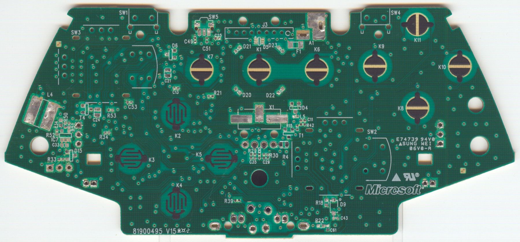
A scan of the Microsoft Xbox 360 controller PCB. (Source: RDC from Acidmods)

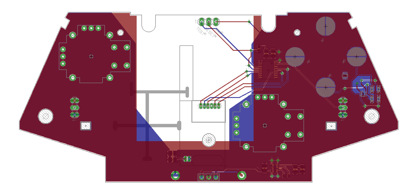
RDC on Acidmods.com has been very kind and has been helping me with the design of the controller PCB. He has created an Xbox controller-compatible PCB before so his knowledge is very insightful. I have also purchased one of his boards called “36X controller” and have been referencing that when designing mine. Because the dimensions are very tricky, I have been using MATLAB to accurately retrieve measurements. It would be pretty much impossible to retrieve accurate dimension measurements using a caliper from the actual board with all the parts on it. RDC actually sent me a screenshot of his own design, and using MATLAB, I am measuring the distance between 2 points at a time in pixels. With a calibration measurement, MATLAB converts pixels into millimeters which then I use in Eagle to place my components. As an experiment, I printed out a 100% scale copy of my PCB from Eagle and laid it over RDC’s 36X PCB and got a perfect match! All holes, critical components are exactly where they need to be. So the MATLAB technique seems to be working great.

3-D Rendering of RDC's X36 PCB. (Source: RDC on Acidmods)

Screenshot of the current state of my remote controller PCB. 

As for the car itself, everything is installed. There are now 2 stand offs that hold the main PCB in place. Also, my super glue solution for keeping the servo in place has failed. So my friend Jeff was nice enough to drill some holes on the car frame so that we could screw down the servo in place rather than depending on glue to hold screws down. You can never go wrong with the old washer/screw/nut combination. Finally, all the LEDs are installed and they work perfectly. They are very bright, and brake lights operate just like they do in a real car. Jeff and I are currently considering installing some police lights on the roof of the car just to make it more bad-ass. Lastly, I will be sanding down the paint on the body of the car and repainting it. I am thinking of painting it matte black, I think it would look very cool. And I want to leave you with these 2 pictures of the car, notice the lights!


Thursday, 14 November 2013

RC Car circuit is now on wheels!!! RC Car Updates 11/14

Hey everyone!

Awesome awesome news! But before that, quick apology for not posting in over a month! The project is still a go at full speed and I have been making huuuuggeee progress.

The circuit board is NOW ON THE CAR! I have made the necessary modifications required to integrate the circuitry to the car chassis. The first mod required was the servo swap. The RC car originally came with a DC motor to steer the front wheels. This is a very inefficient way of achieving steering since it counts on the motor stalling and keeping the wheels fully locked to the either side. This means you get no control over where exactly your wheels are pointing and the stalled motor pulls billions of amps!

The servo swap required me to use some machinery to get rid of the old fasteners that held the DC motor in place. After I got rid of that, I had to drill a new hole through which the servo went through. Finally, I did have to extend the gear piece that came with the servo, by super-gluing another piece of plastic which finally connects to the steering column.

Here is a close up of what it looked like right after I did the servo swap. I did unfortunately use super glue to glue down a couple of nuts to the body on which I screwed the servo in place.

Right after I finished the servo swap.

Before the standoffs and the battery holder were installed.

After the servo swap, the next modification needed was to mount stand-off's on which the circuit board could sit on. For this, I needed the help of my buddy Jeff who has a friggin' wood-working/machine shop in his basement! We got a pair of standoffs that was quite what I needed to we used his tools to modify the standoffs until they became what I wanted :) The standoffs are screwed into the chassis of the car and the circuit board screw into the standoffs. Here is a picture of the car when we were drilling holes into it.

Picture of the car in Jeff's shop.

There are only 2 standoffs and they are both on the same side, however the battery holder also supports the circuit so it should be fine. Speaking of the batteries, I have purchased 8 2300 mAh Energizer AA batteries from Amazon. These are the batteries that powering this bad boy, and I also got a very nice battery holder for them. The battery holder unfortunately does not fit in the original compartment where the old battery used to go, so it sits on top of the old battery compartment. The holder is Velcro'ed on top of the old one and without too much hassle, it is possible to reach the batteries inside without having to deconstruct the whole car. It is still somewhat of a pain in the ass though!

Finally, I do have a demo video for you. Enjoy:


Thanks!

Sunday, 6 October 2013

Great Milestone: RC Car Updates 10/6

Hey everyone,

This is a big milestone in the Crazy Fast RC Car project. The PCB actually works!! There is not a single thing that I messed up on it! I am baffled by the fact that this board works the way it does considering it is only the first revision. We can count this on the numerous times I checked the wires and the connections on the board in Eagle before I got it fabbed, it all paid off.

I must say that I got very close to making a colossal mistake on this board when I was designing it. As you know, there are two LDO regulators on the board, one for the 5V bus, and the other for the 3V3 bus. For the 5V bus, I am using a beefier version of a LS7805 with the same pinout. For the 3V3 regulator, I had originally purchased an LM1117. However, I thought that LM1117 had the same pinout as the LS7805 regulator. It turns out that GND and VOUT are swapped, so this gave me a momentary heart attack when I found out. I thought I would have to fix this and have to get a new revision of the board fabbed, but I was very lucky to find that NTE1904 (which is a 3.3V regulator) has the same pinout as a LS7805. So I ordered one and soldered it on the board and it worked.

I am still waiting on the dual row female headers I purchased 3 weeks ago. I was being cheap and decided to order from China, not knowing it would take this long. I am getting pretty impatient, but once it arrives, I will solder that on the board and have a chance to test all of the functionality of the board. Namely, I still need to make sure my wiring and the voltage divider I made is working as I planned for the optical sensor. You will see in the video that the remote controller device is still on a breadboard. Once I finish up the Main RC Car board, I will start working on a PCB design for the remote controller also.

Go ahead and watch the video below:


Sunday, 22 September 2013

RC Car Updates 9/22: Soldering components on a PCB

Hey all,

I have been soldering the components on the board this past weekend. Soldering can easily become a nightmare when you have a lot of components, especially if they are surface mount parts.

Surface mount parts are much smaller than through-hole components and their footprints are usually much smaller. This makes it very hard to solder surface mount components when compared to their through-hole counterparts. One might choose to use surface-mount (SMD) components over through hole components when space is a limitation on the board. Also, because SMD components are on the "surface", they take up space on only the layer that they are on. Through hole components require "through holes" to be mounted so the hole goes through all of the layers. This means that you can't use the space underneath the component to route wires.

Space became an issue in some areas of my PCB therefore I had to choose SMD parts. However, I tried to use as much through hole components as possible to make soldering easier. There are some simple rules that I follow when I solder up a board. First, I solder the SMD components before I solder the through hole components. The reason is that I use a technique called "reflowing" to solder the SMD parts. This technique requires solder paste, which kind of speaks for itself. It is like solder but comes in a paste form. You apply the solder paste on all of the SMD component footprints first. Usually, you would use what is called a stencil to make this process easier. Stencil is basically a mask for your PCB with only the footprint areas exposed. Then you would use a spatula to apply the soldering paste which would automatically find its way to the footprints. However, stenciling is quite expensive so I did it the manual way. I applied the solder paste on the footprints using a toothpick being very careful and slow. You want to make sure you don't short footprints together by applying too much solder paste. Once this is done, you carefully place the SMD components on the solder paste-applied footprints. Using tweezers are highly recommended for this step.

Once all of the SMD parts are placed, next step is quite unusual: heat up the board. I know some people use heat guns, frying pans etc. I use frying pans. Turn on your stove and let it heat up the frying pan. Then add the main ingredient: the PCB. I really cannot tell you how long to keep the board on the PCB, but how I know is I watch the solder paste. The solder paste is usually gray colored, and when it is "done" it turns into a silver color just like regular solder. This is when I know my PCB is done cooking!! Check out the picture below:

When the soldering paste turns silver, remove the board and let it cool down. Once it is cool to touch, you can start soldering the regular through hole components. I am not going to talk about how to solder, that is very trivial. But I want to share the current status of the board with most of the components soldered.


You will notice that the 3.3V regulator is not populated on the board.... Unfortunately I messed up a little there. I now understand why people say "the first revision of a PCB never works". But mine will!!! It is a recoverable error. I miscalculated the pinouts of the 3.3 V regulators I ordered but I did find that RadioShack sells 3.3V regulators that will work with my board! So I ordered a new regulator right away and I will solder it when I get it. 

Other than that, the only parts I am waiting for are the dual row female headers for the C2000 LP to sit on and SMD LEDs. I have obviously soldered many through hole components already, so I will not be reflowing the LEDs. It also turns out I am very short of through hole ceramic capacitors so I need to order a bunch of those. Overall, project is going really well so check back for more updates! I should be able to test the board in a couple of weeks!

Anil

Thursday, 19 September 2013

Crazy-Ass Fast RC Car Updates 9/19

Hey everyone,

Quick heads-up: The name of the RC car project has officially changed to Crazy-Ass Fast RC Car.

I am happy to report that my boards are finally in! The PCBs were fabbed in China through SeeedStudio. I highly recommend their service to everyone. The boards seem to be really high quality and well built. Despite the really low price, they are looking really sharp. Also as a plus, I received 9 copies of the board even though I ordered 5 boards. So they are also quite generous.

I haven't had a chance to populate the boards yet. There are going to be a lot of components on the board, so it is taking a long while to gather everything needed. I am on a tight budget so I am buying most of the components on eBay shipped from China. The footprints are spaced out perfectly for the C2000 LP! Boards are looking very promising.

Here are some pictures:

Fresh out of the oven.

C2000 Launchpad Sitting on the footprints


Wednesday, 28 August 2013

RC Car Update 8/28

Hell Everyone!

It has been almost 1.5 months since the last time I posted an update! There is finally an update now, and here I am sharing it. The main PCB that will go into the RC Car is ordered! I am using Seeed Studio PCB services to get my board fabricated. The board is about 8cm-10cm, and I am paying $30 in total for 5 copies of the board.

I have finally added the features I have been meaning to add onto the board and created the Gerber files. After carefully reviewing them, I decided it was good to go! I placed the order and paid for it about a couple of hours ago. Bad news is that the boards are being fabbed in China so it could take up to a month until they actually reach me. This my first time working with Seeed Studio's PCB service so I will make sure to let you know how it goes.

On top of that, I have also ordered the transistor that will be used to switch the headlights on the car, the 5V and 3.3V LDOs that will supply power to the components on the board. I am really excited to see that this board is finally getting fabricated after working on it for 4-5 months! I am planning on posting another update when I get the boards from Seeed.
3-D rendering of the main RC car PCB.

Tuesday, 9 July 2013

RC Car Updates 7/9!!

I have another demo today. I have been making solid progress in this project. I am going to keep this one short, so let's get to it.

What's new:

  • The motor controller prototype that I finished building last month is finally being utilized. It is now doing what it is meant to do. The C2000 is fully interfaced with it over MotorA, MotorB and GND lines. I am now utilizing the vertical axis of the joystick to control the DC Motor. Click-in of the joystick does motor braking (very cool).
  • I purchased a DC motor. I bought it just so I could try out the system. It is very big, but not probably not the most efficient or the fastest motor. So it will do for now, but for the real deal, I am going to invest around 20-30 dollars for a very high speed DC motor. I will throw heat sinks on all transistors, so I should be able to pull 5 Amps continuously. (The only limitation is cooling...)
  • I purchased a new servo motor. This servo pulls 1.4 Amps when the rotor is moving so I had a hard time finding a power supply beefy enough to power the servo. When I try to power it from my PC or my 1-Amp phone charger, when the servo pulls current, voltage drops and the C2000 does a brownout reset, kind of funny :)
Aaaaannd here is the demo. Enjoy ;)


Saturday, 22 September 2012

Programming the MSP430 using Assembly

Hey everyone,

From those of you who are in Prof. Khan's ECE2560 microcontroller's class, I have been getting a lot of questions on how to load the assembly project examples onto the MSP430 Launchpad. For this tutorial, I will use the Blinky.asm.

To start, go ahead and start up CCS v5. Do note that in order to be able to program the MSP430 Launchpad, you will need to be on the Free Code Size Limited license.

1) To create a new project, go to File>New>CCS Project. Make sure you choose CCS Project and not just Project!

2) Look at the screenshot below and make sure that you make the same selections. Make sure that you have MSP430 selected as your device, and MSP430G2553 as your variant. Also Choose Empty Assembly-only Project as a template. You can name your project as you wish, it does not have to be Blinking_LEDs.


3) I called my project Blinky. The next step is to create a source file into which your code will go. This file can have various formats, it can be a ".c" file, but we want a ".asm" file because we will be using not C, but assembly to program. To do this, find your project under the Project Explorer and make sure its title is in bold. Right click on its name and choose New>Source File. If you are lost, check out the screenshot below. When the New File window comes up, find a name for your source file and make sure to add .asm at the end of it. For example, I chose main.asm as my source file name.


4) Once the new source file is created, the new file will open up in the editor. But you will notice that it is not empty. It puts a couple of lines in the file which include the date and your name. You can see a picture of it below. Delete all of these lines because if you leave them there, your compiler will give you errors. This title would work fine if we were programming in C, but assembly compiler will not be happy.


5) Once you deleted the lines, go to this PDF file  here. You might notice that this is the PDF file on Prof. Khan's website which contains the example code. You will see that the code is copied directly from CCS into the PDF file. You will also see that line numbers are also present. What you can do at this point is copy all of the text and paste it into your new .asm source file on CCS. However, you are not quite done yet because you will need to reformat the whole code in order to be able to compile it. You will see that every line is messed up and the indentations are all wrong. You can try fixing it, but don;t even try because I am nice enough to provide you with this text file which includes the same code, in the correct format. I have done all of the manual labor for you. So all you have to do is open up the .txt file, copy the contents and paste it into your source file on CCS.

6) Once you have that done, all you have to do is debug your code and program your Launchpad. To do this, click on the button that has a bug on it and this button will build, compile and program your code. So it is a pretty useful button, isn't it? If you don't know which button I am talking about, check out the screenshot below.


7) Once CCS finishes programming your MSP430, you will have to command your MSP430 to execute your code in order to see your LEDs blink. To do this, click on the button that looks like a play button. To end your debug session and go back to editing your code, click on the stop button. Here is a screenshot that shows where these buttons are located on the CCS Debug window.


Common Problems
Some of you will inevitably run into problems during debugging. The most common problem will be that you have the wrong license on CCS so you will get a message saying that you cannot program MSP430s with your current license. To fix this, go to Help>Code Composer Studio Licensing Information. Then go to the Upgrade tab and choose Launch License Setup. Once the License Setup Wizard comes up, click on CODE SIZE LIMITED (MSP430) and then click on Finish. Now you should be able to debug your code.

Have questions? Comment below and ask them. I will get back to you.

-Anil